Home Power Systems

Electricity from the Sun, Wind and Water
Return links:
Return to Home Page
DC Hydro Systems 
> AC Hydro systems 
Solar Equipment 
Basic Electricity 
Formulas & Tables 
Communications 
FAQ & Answers 
Equipment sales 
Contact and Forms 
 'Aqua Sheer' Coanda screen intake. Head tank on a 60 kW hydro system 580 kW turbine runner Generator and Turbine on a system built by SunWater Power Systems/Homepower

On this page:     Working AC projects:  ---  AC Systems Overview ---  Photos


   AC direct projects, no battery storage:


Home Power System # 1


Future site of power house, water will drain into pond stocked with fish.
Future site of power house, water
will drain into pond stocked with fish.

Construction of the power house.

Wiring the electrical panels.
Wiring hydro control panels. The heater
below is part of the governor load control.

Installing the turbine to the penstock.
This is a two nozzle pelton wheel.

The generator is coupled with a belt.
The generator is coupled to the turbine with
a belt to best match the water jet velocity
to the generator.


     Statistics:
  • Turbine: Eight inch overhung pelton
  • Generator: 10 kW Lima alternator
  • Operating Head: 200 feet
  • Rated flow: 200 gpm
  • Operation voltage: 120/240 single phase
On this large rural property a micro hydro had been the owners wish for many years. Although supplied by the grid, the desire was to try to live off grid as much as possible. So in 2010 work began. The penstock had been built earlier, so the power house was built to couple to the pipeline most easily. In order to best match the water velocity to the requirement of the generator for 60 cycle output, a belt drive was used.

As with all of these AC systems, electrical load is what maintains the generator speed at exactly 1800 RPM which is needed for 60 cycle AC output. This is what load control governors do. By constantly monitoring line frequency, the governor maintains a precise amount of load to match the power output of the turbine. Excess energy is converted to heat in a water load tank or air space heaters.

Governor interior
An inside look at the electronic load control governor.
This unit included active load management.
This feature enables more load to be
connected than the generator is rated for.


Trout in the tail race pond
A large stocked fish pond is supplied from the
tail race water. Note the large trout.


Farm animals abound.
The property is also home to many ctitters.


Home Power System # 2


The secondary filter box. Air is the enemey of impulse turbines.
Air is seperated and a final filtering before the long drop.

Steel 4 inch penstock during installation.
The 4 inch steel pipe was held in place with rope on the side hill during construction.

The power house is just 250 feet from the lodge, and is virtually silent.


     Statistics:
  • Turbine: Ten inch overhung pelton
  • Generator: 14 kW Lima alternator
  • Operating Head: 550 feet
  • Rated flow: 200 gpm
  • Operation voltage: 120/240 single phase
With a 550 foot gross head, this system produces up to 14 kW on a maximum of just 200 gallons per minute. The turbine is governed to 1800 RPM with a THES Junior series control. A 1700 foot long, 4 inch diameter polyethelene and steel penstock drops 550 feet from an air seperation box to the power house. Between the source and box, there is 7,200 feet of pipe from an intake at the 1500 foot elevation.


This 7,500 square foot lodge is being powered
by a 14 kW turbine. Careful load management
prevents over load.


With limitless clean water, this turbine has been
on line since 2003 without any problems.


The generator outputs 4160 volts. It feeds a 2 kM long under sea cable to the camp transformer.
The generator outputs 4160 volts. It feeds a 2 kM long under sea cable to the camp transformer. Hand showing off one of the output terminals - during construction.


The intake dam at 1200 feeet elevation.
The intake dam at 1200 feet elevation in flood conditions. There is 80 yards of concrete in this dam.


Home Power System # 3

     Statistics:
  • Turbine: 24 inch Pelton
  • Generator: 750 kW 3 phase 4160 volt
  • Operating Head: 1200 feet
  • Rated flow: 11,800 liters per minute
This project was built by various contractors, and at a cost of 2.5 million dollars is beyond the scope of most home owners. It is included as an great example of larger systems available. Homepower's part was in the initial surveys and exploration, feasibility study, and data collection. Once it was up and running, we installed web cameras and a web based remote monitoring system.

The turbine and generator during installation.
This was all build and installed by contractors.
For the complete story on the building of this project and lots of pictures, go to www.malibuhydro.com


A coanda screen and drop type intake supplies 50 liters per second to a 6 inch penstock, 6000 feet long with 1500 feet of total fall.
A coanda screen and drop type intake
supplies 50 liters per second.


The head tank at top of penstock, a 550 gallon Poly tank. Used for getting rid or air and as a pressure break.
.
The head tank at top of penstock, a
550 gallon Poly tank. Used for getting
rid of air and as a pressure break.


We used 5500 feet of 6 inch polyethylene pipe and fusion welded it into 700 foot sections, joined by flanges.
.
Welding part of the 5500 feet of delivery pipe. It takes a lot of hard effort and dedicated workers to pull this off.

This small chain saw head attached to a capstan winch. We used a 500 foot long length of 3/8 nylon rope to pull the pipe up the hill.
.
This small chain saw head attached to a capstan winch. We used a 500 foot long length of 3/8 nylon rope to pull the pipe up the hill.

Home Power System # 4

     Statistics:
  • Turbine: 14 inch single nozzle pelton, 1200 RPM
  • Generator: 75 kW single phase Kato
  • Voltage :120/240 and 600/600
  • Operating Head: 600 feet
  • Rated flow: 56 l/s
This is a really fabulous system. It uses a huge 75 kW generator oversized for the job, and turning at a slow 1200 RPM. The turbine is massive, built with 1 inch steel plate, a 3 inch shaft and huge bearings. The runner is stainless and has a single nozzle on an hydraulic controlled spear jet. The deflector is also under hydraulic control and will shut the system down in 5 seconds if there is a problem. The governor integrates perfectly, reducing water when power demand is low, and diverting excess power to a 60 kW water load dump. The 120/240 is stepped up to 600 volts for the 700 foot distance to the load.

Wiring the 75 kW generator coupled to 60 kW turbine. Hydraulic controls on spear valve and deflector for fully automatic control. Turbine sump still visible, later covered with access hatch.
.
75 kW generator coupled to 60 kW turbine. Hydraulic controls on spear valve and deflector for fully automatic control. Turbine sump still visible, later covered with access hatch.

From right to left, 75 kVA  240 to 600 volt transformer, main disconnect, governor control panel, distribution breakers, fiber optic terminus, head level control.
.
From right to left, 75 kVA 240 to 600 volt transformer, main disconnect, governor control panel, distribution breakers, fiber optic terminus, head level control.

Big machines are essential on projects like this. Here the excavator lifts 2400 pounds of 8 inch steel pipe into place.
.
Big machines are essential on projects like this. Here the excavator lifts 2400 pounds of 8 inch steel pipe into place on a 45 degree slope.


The secondary filter box. Three screens prevent small particals from clogging the spear nozzle 500 feet below.
Clean water is essential in high
head systems operating with
small nozzles.

Power house with the Lima 12 kW, three phase generator, two nozzle pelton wheel together with control and switch gear.
An example of a very well designed
power house. The tail race enters the sea immediately to the right of the picture.


Home Power System # 5

     Statistics:
  • Turbine: Ten inch overhung pelton
  • Generator: 12 kW Lima alternator
  • Operating Head: 500 feet
  • Rated flow: 200 gpm
With a 500 foot head, this system produces up to 12 kW on a maximum of just 200 gallons per minute. The turbine is governed to 1800 RPM with a THES Junior series control. A 2300 foot long, 4 inch diameter polyethelene and steel penstock drops 500 feet from a filter box to the power house. This project was featured in an article for Home Power Magazine, issue # 76


Installing the heavy turbine took a concentrated effort with willing helpers
The concrete base was poured with the tail race pit incorporated. Careful measuring enabled us to drop the turbine base flanges into the square hole. Rock bolts were also added to prevent any movement.


The turbine control and switch panels. automatic shut down in case of trouble is essential in most hydro installations.
Operating voltage and phase current is displayed on center panel, as well as over/under voltage and frequency alarms. These alarms also shut the system off at the first sign of trouble. The kW hour meter is a nice addition enabling the total energy used to be counted.


A water tank with multi elements to absorb all the 55 kW the system is capable of producing.
This 12 element tank made by DTL Hydro is capable of absorbing the entire output of the turbine as part of the governor's action to maintain correct generator speed.


The 12 inch diameter penstock drops 100 feet to the turgo turbine.
Old 12 inch steel pipe drops 100 feet to the power house.


Home Power System # 6

     Statistics:
  • Turbine: 21 inch pitch Turgo
  • Generator: 25 kW 3 phase Stamford
  • Operating Head: 100 feet
  • Rated flow: 1000 gpm
Another remote home site which has never had to depend on a gas or diesel generator. This is large enough to provide power for several homes, and excess energy is used to heat hot water for a hot tub. This site originally had a large 48 inch ancient pelton wheel and 125 kW Westinghouse open frame generator. This was later replaced with the equipment shown here. DTL Hydro built and installed this equipment shown here. Our job was working with the contractor comissioning the the upgraded electrical system. If you want to have us on hand and use your own electrical contractor, that is fine.


The turbine is belt driven to the generator. Water discharges below the turbine inot a 3 foot diameter culvert extending out to the river.
The turbine spins at just 240 rpm and
uses a belt drive to the generator.


Top

Alternating Current Systems Overview:
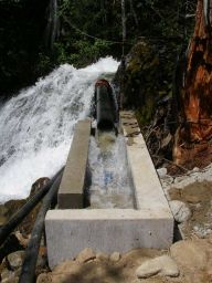
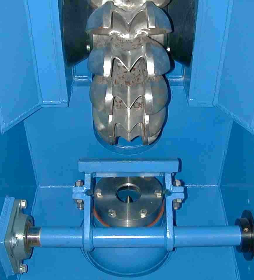
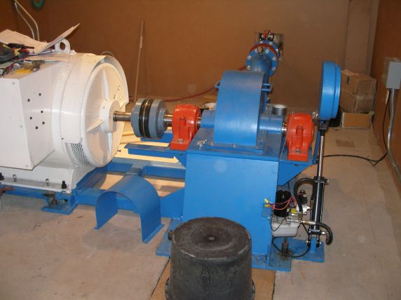
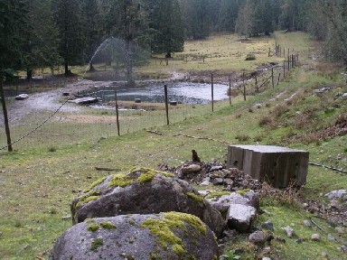
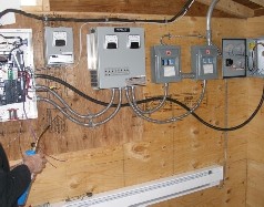
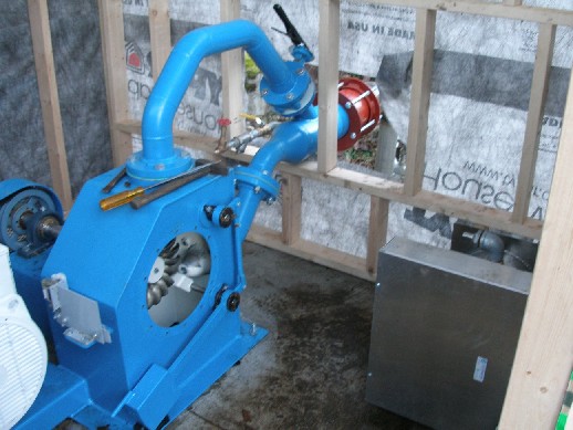
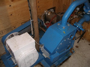
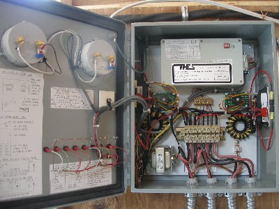
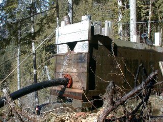
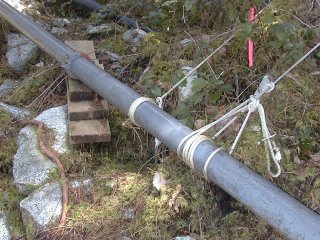
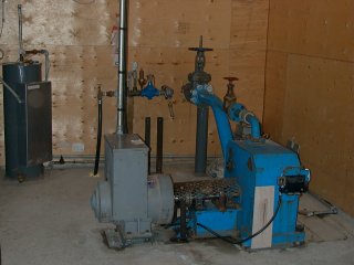
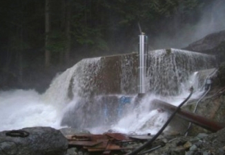
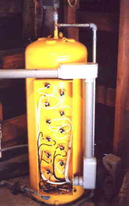
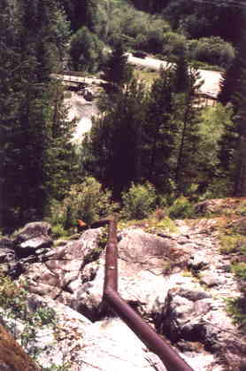
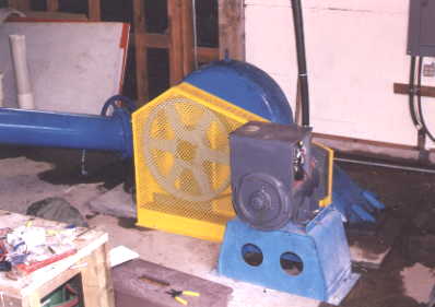
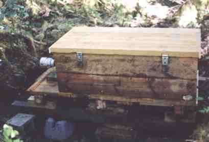
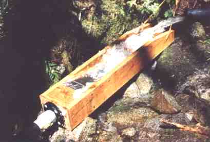
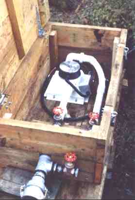
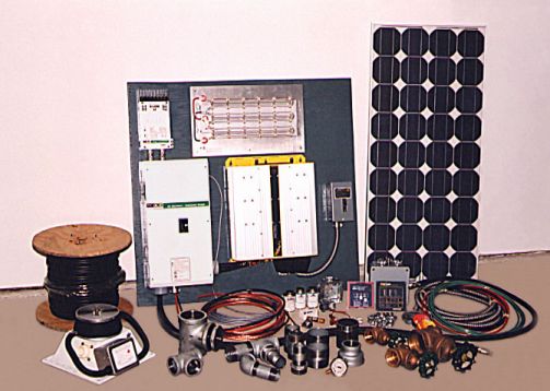
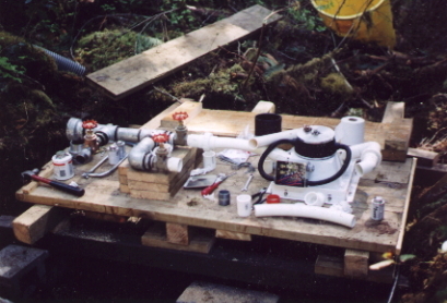
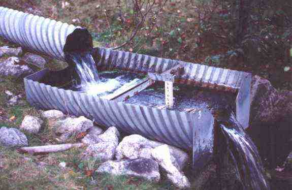
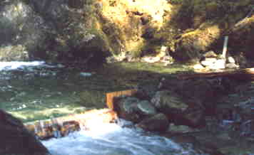
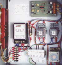
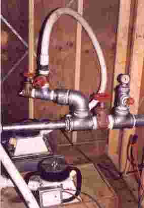
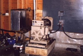
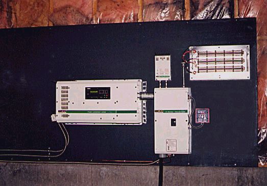
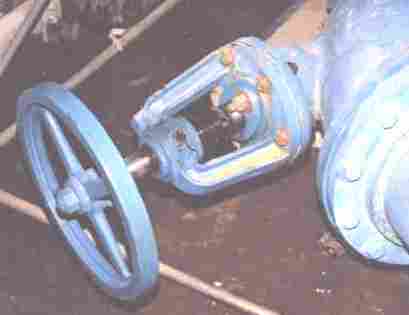
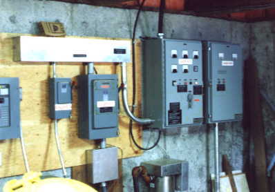
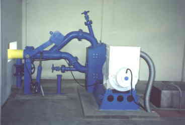
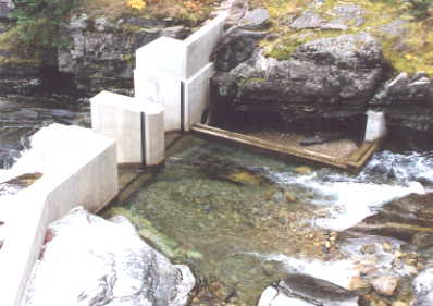
Water to wire.... how the electricity is generated.       (See below for hydro definitions)
The following text explains the key components in a typical installation.

Water intake:
The process begins with the water in the creek having a potential energy equal to its mass times its height above the turbine mounted on the power house floor. The water is slowed in a pool so the sand can settle out. Larger debris is also filtered out here. Excess water passes over a low weir, or barrier, with a controlled amount entering a large pipeline or 'penstock'.

Penstock:
Water flows down the pipe at a slow rate of speed, typically 5 feet per second. The pressure steadily increases in proportion to the increasing drop. It is the high pressure that forces the water out the nozzle. The actual rate of flow in the penstock is relatively unimportant, unless the pipe is very long in which case an excessive amount of friction is created by the flowing water.

Turbine:
This is the heart of the energy conversion process which changes the waters velocity into mechanical energy. Water striking the curved blades of the turbine imparts its kinetic energy of motion on the blades. The turbine spins at slightly less than one half the jet velocity, and falls away from the turbine with virtually zero energy.

Spear Nozzle:
Manual control of the power produced can be made by adjusting the amount of water passing through the turbine. This is accomplished by adjusting a threaded spear which screws into the nozzle assembly where the penstock enters the turbine. This pinches off the flow in any amount required. Typically, the control is set to the maximum power required, and the governor then maintains control by dumping any excess power.

Generator:
Within the generator there are many coils of wire wound on iron cores attached to the generator frame. Rotating inside these coils is an iron core which produces strong magnetic fields. As the core rotates at 1800 revolutions per minute, the magnetic lines of force pass through the fixed windings. It is this process that produces the alternating current electricity. This same principle is used in all electric generators, from large hydro and nuclear plants to the alternator in your car, although the speed can vary depending on the type of generator used.

Governor:
This is the main controller for the entire system. Precise powerline frequency is controlled by keeping an exact amount of load on the generator. This load must exactly balance the energy being delivered to the turbine. This is accomplished by rapidly switching on and off ballast loads in a water filled load tank. A second function of the governor panel is to report all the conditions of the system, and any alarms that may result from improper operation. In the rare event of a system alarm, the governor will immediately shut the whole system down by activating a jet deflector which diverts the water jets away from the turbine.

Load tank:
This is generally made up of a large water tank, or series of separate tanks containing electric heating elements. Excess power is shunted to these elements from the governor thereby "putting the brakes on" the generator. This excess power is often used to heat primary domestic hot water in smaller, separate water tanks, one large central tank, or as a low priority source of heat for a pool or sauna. As lights are turned off in the buildings, the power is immediately directed to the ballast load to maintain the exact balance necessary for precise frequency control. Over the course of the night, large amounts of hot water can be produced and stored for use during the day. This method of frequency control maximizes the hydro plant capacity and reduces or eliminates the need for fossil fuel boilers.

Active Load management:
The secret to how a 200 kW hydro plant can provide power to a total load of 300 kW or more. In addition to the governor controlling the precise speed of the generator and hence line frequency, load management diverts available power to useful loads arranged in a pritorized sequence. The load manager is always testing the power being dumped in the ballest load and when there is sufficient excess, another prioritized load turns on. These consist of water tanks, space heaters, display lighting, dryers, freezers, or any other load that can be shut off for a period of time with no ill effect.
Base loads such as lighting, pumps, outlets, kitchen appliances, sound equipment, computers, communications etc. are always connected.


Load Center:
A load center is basically a large switch with up to 24 smaller switches serving as circuit breakers. These will protect the wires and equipment from potential short circuits or overloads. You will have a similar 'electrical panel' in your home. Each building has a load center, and each load center will supply power to all the branch circuits in that building.


Definitions used with Micro Hydro
Here is an (incomplete) list of common terms and their explanation.

  • Static head
    The total available drop from intake to turbine nozzle.

  • Net head
    The useable head after subtracting losses from pipe friction etc.

  • Flow
    The quantity of water being used to produce power. this is usually measured in units of cubic feet per second, gallons or liters per second.

  • Power
    The rate of doing work, or energy expended per unit of time. Often used inter-changeably, thought not technically correct, with energy.

  • Energy
    The ability to do work, energy can be potential as in water behind a dam being acted upon by gravity. Energy can also be kinetic, that is, the combination of mass times velocity, as in moving water in a penstock.

  • Kilowatt
    One thousand watts - Joules etc

  • Volts and Amps
    The units of electrical pressure and quantity

  • vars
    The combination of volts and amps acting in a reactive circuit, that is, one that is either inductive, as in the case of a motor load, or capactive, as in the case of some forms of electronic loads. Vars are like Kilowatts, but since the volts and amps are out of phase, the product of the two is not the same as if they were acting on a non reactive circuit.

Top


   Additional photos of typical installations.


Turbine equipment box locked up.


Coanda screen at provincial park.


30 Amp, 12 volt Stream engine.


Fusion welding machine for
welding 4 inch poly pipe.


Power panel with 250 amp DC disconnect switch, 3000 watt sine wave inverter, together with 80 watt PV panel and hydro turbine together with all fittings.


Laying out the intake manifold before
box is built.


"V" notch weir for measuring flow.


Simple weir in a mountain creek.


Head level control system using 900 MHz radio link.


Two turbines in parallel.


6 kW diesel generator.


4 kW sine wave inverter.


Installing a 12 kW system, needs many willing helpers!


Power house for the 12 kW pelton generator.


A 10 kW turbine, three phase
generator, and controls.


Spear valve control on a large Turgo turbine.


Switch gear used in typical 50 kW sized hydro system.


A dump load used to regulate generator speed.


100 kW, two nozzle pelton generator.built
by Dependable Turbine Ltd.


One man hand made this concrete dam
for a 180 kW system.

Top


Contact Information:
Phone 604-465-0927
Email: